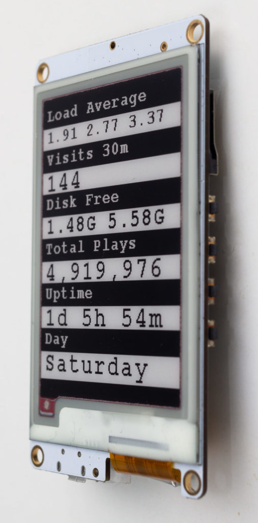
I created a case for my ESP32 E‑Paper Status Display using Fusion 360, Cura and a 3D printer.
It is available to download at Thingiverse.
I created a case for my ESP32 E‑Paper Status Display using Fusion 360, Cura and a 3D printer.
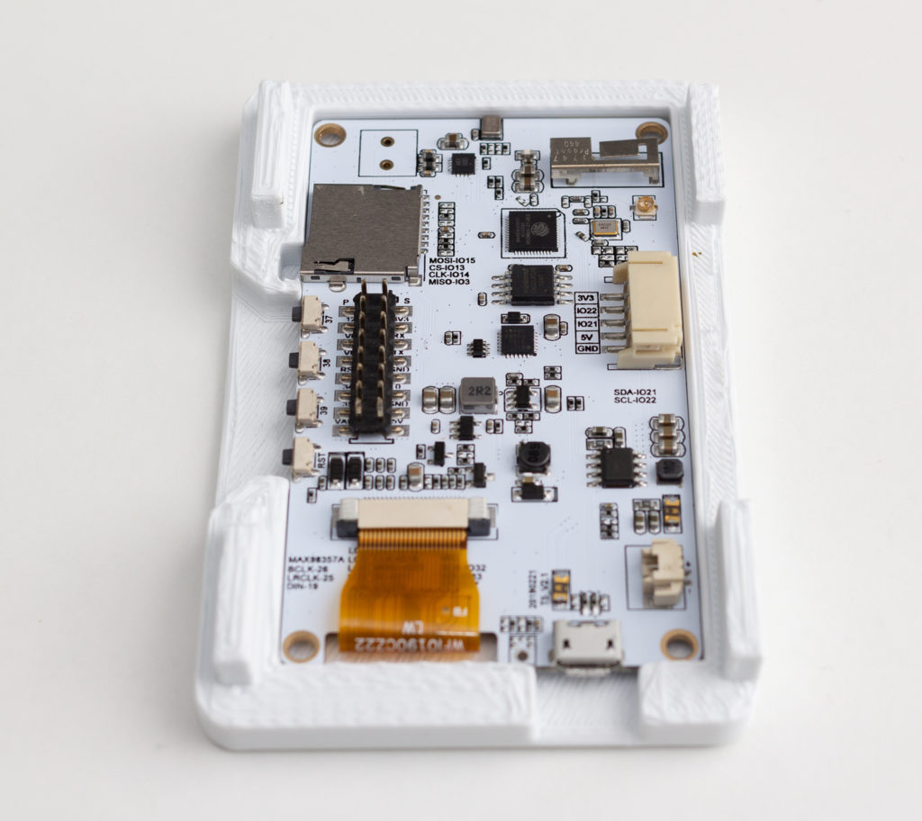
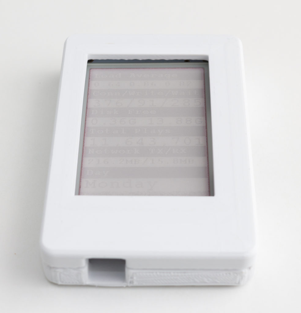
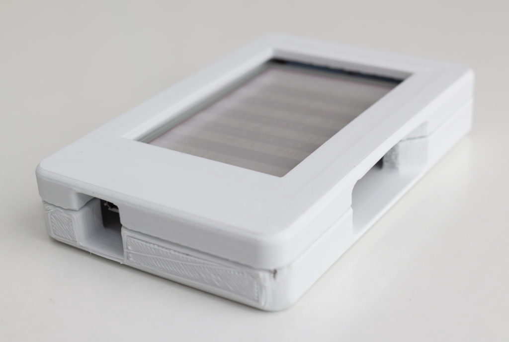
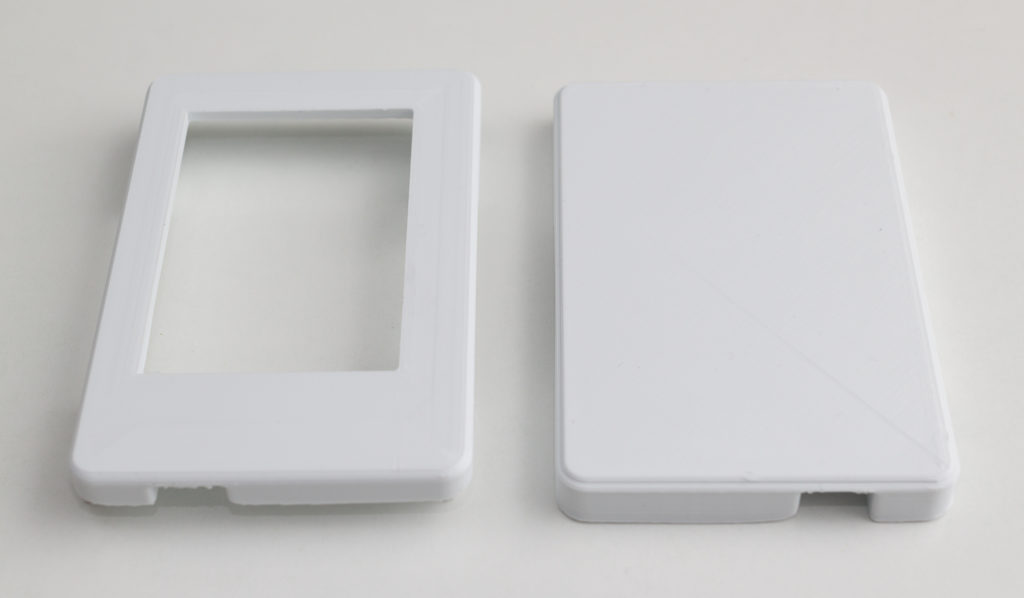
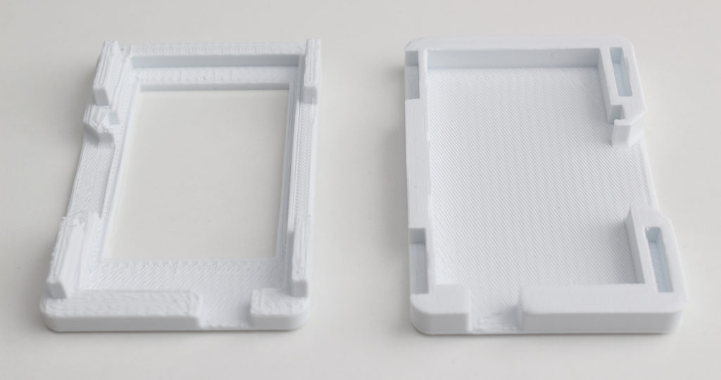
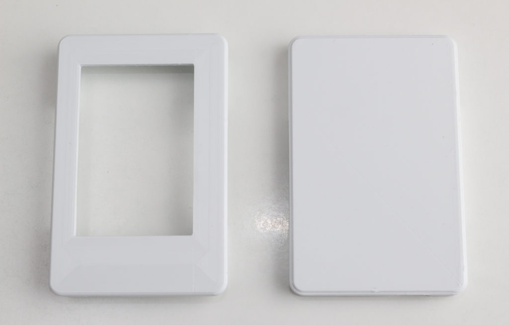
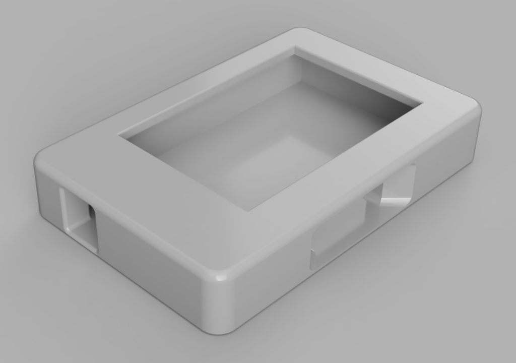
It is available to download at Thingiverse.
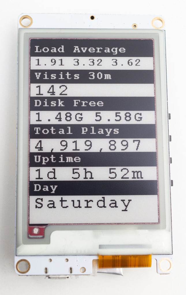
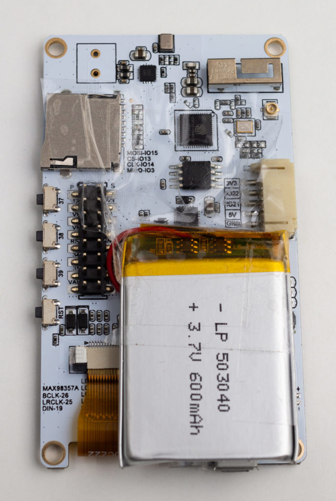
Using an ESP-32 board with an embedded E‑Paper display, I created a gadget that shows status information from my web server.
E‑Paper, also known as E‑Ink, only needs power when being updated, and uses no power between updates. This means that the gadget can be powered for weeks from a rechargeable battery.
The purpose of this gadget is to put on my wall or desk, and show regularly updated important information on my web server, to keep informed of web site problems and statistics. The information displayed can be easily changed, for example to the latest weather, news, currency prices or anything that can be accessed via the internet. E‑Paper means it uses a very small amount of power and heat, compared to a computer display or television.
You can view my code on GitHub if you are interested in making your own.
Today I used an Arduino reprogrammable electronics board and a GSM/GPRS modem to send data to the Internet. This will be useful for the sensors I intend to build.
You can see a video of it operating below. One window shows the output from the serial interface as it makes a request to my web server and outputs the response, and the other window displays the access logs on my web server.
I used a software UART (parallel and serial data converter), as using the Arduino’s built-in serial interface caused conflicts. Learning to use a software UART is going to be very useful for the next step in the project.
I did consider making a Cat Facts for Arduino, but I resisted the distraction.
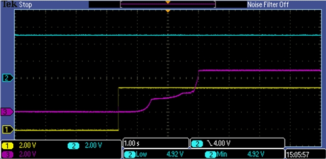
I didn’t have any issues with power spikes causing a reset (the GSM board uses a lot of power) as this is a version 2 board with soft start circuitry:
I also used AT codes to send SMS text messages. A full list of AT codes are available here, and I used these:
Set to human readable text mode:
AT+CMGF=1
Set phone number:
AT+CMGS=“447944581307”
Enter the message
Send hex 1A to escape message.
AT+CMGL
AT+CMGR=<index> (indexes start at 1)
AT+CMGD=<index>
The only stumbling point I had was when the GSM modem was set to a different baud rate than my software serial interface. To change this, I sent the AT command AT+IPR=9600 to reconfigure the modem.
I learnt that AT commands are also used to send and receive via TCP/UDP. This made it much more straightforward than some kind of low level system I had imagined. All that is required from the Arduino is to send AT commands (e.g. AT+CIPSEND=) and listen for incoming responses.
—
I made an electronic circuit that can send information to the Internet. This will be useful for making a sensor e.g. a temperature sensor for an office that is accessible on any computer/smartphone.
Atmel Studio now has an extension designed as a simple alternative to the Arduino IDE.
The Arduino IDE is relatively simple. It is great to get started with AVR programming, and has some useful examples to get you started, but lacks many of the features that experienced programmers call for like detailed compiler warnings, debugging capabilities, auto-completion and unit testing.
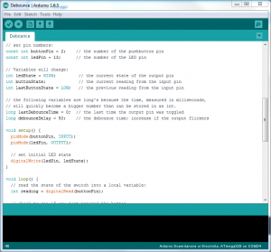
Programming for AVR at a lower level in Atmel Studio can also have performance improvements. Shifting bits rather than using Arduino IDE’s ‘digitalwrite’ can have a 10x speed improvement for example.
Atmel Studio supports a wider range of AVR microchips. This can be useful if you aim to program one of Atmel’s huge range of microchips. I have a ATtiny13A, which uses considerably less power than the ATMega328 in my Arduino board (190 µA in active mode, and 24 µA vs. 0.2 mA in active mode, 0.1 µA in power-down mode, and 0.75 µA in power-save mode).
So if you feel you are outgrowing the Arduino IDE, give Atmel Studio a try. You may find this tutorial useful: Using Atmel Studio 6 with Arduino projects, or How to Setup Atmel Studio for Arduino Development.
Simplicity can be more important though, and the Arduino IDE may be more suitable for your application. After all, projects are generally relatively simple when you have less than 16 KB of memory to play with. I expect I will continue using the Arduino IDE primarily, and Atmel Studio for any particularly challenging projects.
Arduino refers to a few types of tiny electronic board with a reprogrammable microchip. Programs can be sent from a computer to this microchip to perform whatever task is required.
A fun example is Leah Buechley’s Turn Signal Biking Jacket project, shown in the video below:
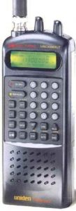
When I was growing up, one of my favourite birthday presents was a Uniden UBC3000XLT radio scanner. I enjoyed finding and listening to various radio transmissions, and I had some success decoding data transmissions and morse code using my PC and Sound Blaster soundcard.
I was interested to read about a technique called Software Defined Radio (SDR), which can sample the entire shortwave spectrum, and use the processing power of a computer to virtually ‘tune’ in to transmissions.
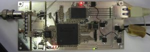
A home-built SDR board operating at the University of Twente in the Netherlands (pictured below) and a receiving element around 5cm x 10cm is capable of receiving a frequency range of 0 — 29.160 MHz.
It uses a Spartan XC3S500E Field-Programmable Gate Array. FPGAs can be programmed using a hardware description language, and arrays of programmable logic blocks which can be virtually inter-wired. The most important advantage over a microcontroller like a Atmel/Arduino, is these operations can happen in parallel, which is critical to creating a software defined radio, as a typical AVR microprocessor simply doesn’t have the necessary clock speed. The sample rate must be at least twice the maximum frequency of the signal (Nyquist theorem).
Taking this a step further, Software Defined Radio can allow multiple users to share the same receiver. At time of writing, 184 users are listening to different frequencies using the receiver at the University.
You can listen for yourself at the Wide-band WebSDR at University of Twente. It’s essentially a free radio scanner anyone can access for free. You might enjoy stumbling upon a variety of transmissions from all over the world, and you may have success using tools like Sorcerer to decode data transmissions, weather fax transmissions, and morse code.
With the ever-continuing advances in data storage capacities and scalable clouds, one day it may be a trivial matter to archive the entire radio frequency spectrum.
Here is a useful function to read DIP switches with Arduino. Wire the switches to ground, as this uses pull-up resistors:
Be sure to check ” and ’ symbols haven’t been made fancy by WordPress, or you’ll have errors in your code.